| |
|
        |
|
 |
 |
 |
|
| FAQsMallory Ignition Systems FAQs | |||||||||||||||||||||||||||||||||
| links to other FAQ pages [ V8 Engine Fitting Information ] [ Rover 3.5, 3.9, 4.2 to 4.6 Conversion ] [ LPG Conversion details ] [ Fuel Injection Section ] [ Weber 500 & SU Carbs ] [ Mallory Ignition Systems ] [ General Engine Problems ] [ General Information ] |
|||||||||||||||||||||||||||||||||
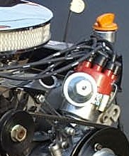
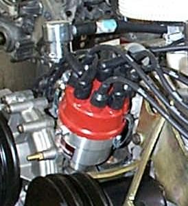
The following information is designed for you to get the best from your ignition System. We would welcome any further feedback from you. Back to main ignition pages. 'Click' Wiring Diagram for Mallory Distributer 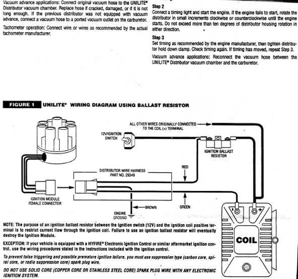 Don't worry if your coil doesn't look like this American one, or your connections are not the same, it is, however, clear to see how simple the Mallory is to add to your existing system. Our A&R amplifier can also be used with all Mallory ignition or as an amplifier unit replacement for all Mallory distributors, for upgrade or in the event of O/E amplifier failure. We asked Mallory why we sometimes get a problem with the capacitor failing, and subsequently causing loss of spark, or points to burn out early. They replied with. There are a couple of things to check ... > > First, we have seen problems when a customer replaces a condenser. If he continues to reuse the old bracket or does not tighten it properly, he may not be getting a good contact with the housing. The condenser has a coating to prevent discoloration on the outside of it. When the bracket is tightened down, it scratches through the coating and make a good contact. I suggest the customer take a new condenser, scuff off the coating with a very fine sandpaper, then install it using the new bracket we supply with the condenser. Make sure he tightens the bracket and not just snugs it enough that the condenser will not fall out. Quite often, the problem will disappear. As for a replacement that can be used, there really isn't a more heavy duty piece available. The rating needs to be .28 mfd. If you are having failures like you are describing, I would check for a bad or poorly matched coil, bad plug wires, and bad grounds. Condensers, once they are functioning, do not normally just fail on their own. Let me know what you find. Thanks, Mike (Mallory) FAQ Dear Chris, I have an excellent Mallory dual point distributor and I wish to convert it to an electronic ignition, is this possible? Yes it is! The A& R Ignition amp that RPi produce not only increases the output of all existing electronic ignitions, (as seen on our pages) but it can also be utilised to turn the Mallory dual point into a fully fledged electronic ignition, whilst retaining the extra 10 degrees dwell created by the dual point switching. In essence the ignition still works as a dual point but the A&R amp takes away all the voltage from the points and capacitor (condenser) thus achieving an even higher output than normal, and completly eliminates capacitor failure and points burning. Please see these two links to our pages on our A&R amp, Power amp (Non LPG) and A&R Power amp Dual Timing (LPG/Dual Fuel) |
|||||||||||||||||||||||||||||||||
|
|
|||||||||||||||||||||||||||||||||
|
|||||||||||||||||||||||||||||||||
|
|
|||||||||||||||||||||||||||||||||
1. Engine Idle/rpm picks up and decays continuously. 2. Engine cuts under load (this is when vacuum is strongest).
These adjustments are not normally essential but further improve the performance of your Mallory ignition system, and should be regarded as an extra level of efficiency and performance that can be achieved by modifying available Rover ancilaries to further enhance your engine's specification.
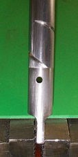
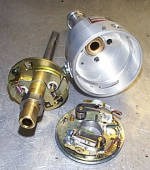
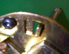
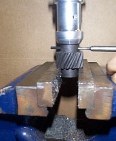
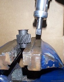
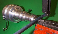
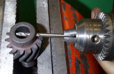
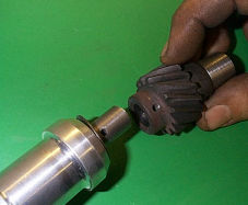
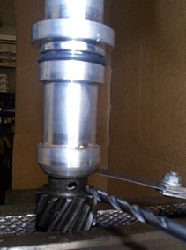
While the following may seem bewildering to some, we can supply the Mallory with the new drive gear already fitted for an additional £45 (if so, ignore the following) or for those with Pre-1976 engines, the Mallory drive gear does not need changing. Instructions for Changing to later type Oil pump Drive gear.
Q: What should the Centrifugal advance limiting
bolt under the Mallory base plate be set to for a Factory V8?
A: If the engine is stock, then the maximum is 28deg. advance allowable by the Dual Point Mallory. I find that 34-36 degrees total advance provides good all round performance. The stock Mallory distributor ships with 24 degs advance and can be adjusted to provide from 16-28 degrees. Q: With the Dual Point Mallory, what should the
initial advance be at idle (vacuum advance line disconnected &
plugged)?
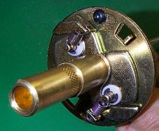
A: Approximately 6-10 degrees BTDC at 1000rpm. Q: How do I adjust the points gap, and what should
the dwell of the primary points set be?
A: I find it is more accurate to set the point gap via dwell rather than via the traditional method of gapping with a feeler gauge. However, the gap with a feeler gauge should be between 0.019" and 0.022". To set the points gap via dwell, use an Automotive Multi-Meter with a Dwell function. The dwell of the primary set of points (first firing) should be 26-28 Degrees. This is measured by blanking the secondary (or trailing) points with a small piece of card, then turning the engine over with the dwell meter connected. Based on my experience, I take the highest reading shown as it is difficult to measure dwell accurately when cranking as the numbers tend to vary 1-2 degrees at such low and inconsistent speeds. I have found on a variety of cars with no external dwell adjustment (unlike the Lucas factory V8 distributor) that by taking the highest reading when cranking you will get quite close to the actual dwell you would see when running. Q: What should the dwell of the Secondary points
set be?
A: It is easier to set the 'Combined' dwell rather than setting the dwell of the Secondary set alone. It can be done of course by simply masking the primary, then checking the secondary dwell is set to 26-28 degrees, but it is simpler and more correct to remove the blanking from the secondary set of points after setting the primary, and then checking the combined dwell is set to 33 degrees by adjusting the gap of the secondary set. Simply adjust the points gap of the secondary set until you see 33 degrees on the dwell meter then you are done. Start the engine, make sure it is running at a normal operating temperature, then measure the dwell, it should be rock steady within say a 2/10th of a degree, +/- 2 degrees either side of 33 degrees. Q: What are the felt pads that sit between the
cams on the distributor shaft and the contact set arm?
A: They are there to provide lubrication of the shaft, the points should not be affected.
Q: I presume the Unilite has it's own amplifier.
But is it inside the distributor?
A: Yes. Q: Looking at the Unilite wiring diagram in the
FAQ section, the Unilite ignition module female (connector) connects
to what looks like the plug that fits onto my std distributor
amplifier module. Am I correct?
A: If you look at the Unilite wiring diagram, you will be supplied with the coil and ballast resistor for the wiring harness. Q: I've already bought you're A&R amp but because of the
std. distributor problems I've not fitted it yet. I understand
I can still use it with the Mallory Unilite. Will fitting it
with the Unilite make a significant difference to the sparks
or would I be better off installing it as a backup? Q: I presume the Magnecore leads that I've already
fitted will be fine with the Unilite?
A: We use the Magnecor leads all the time and have never been let down. Q: I understand the Unilite distributor is normally
supplied without the drive gear but you can supply it with a new
gear fitted?
A: Yes we can supply it with a new drive gear fitted for a small additional fee. Q: According to the Haynes Range Rover manual,
if I mark the positions of the rotor arm and the body of the std.
distributor relative to the rest of the engine before removing
it I should be able to put the distributor back in the same position.
If, when I put it in, I match the position of the Mallory Unilite
and rotor arm to the std. unit would that be ok as a starting
point?
A: When you remove your existing distributor chalk/scratch a mark elsewhere showing perhaps where the vac advance was pointing and where the rotor was pointing, then when you withdraw it you will see the rotor twists on the helical gear and finally points to another postilion, use this as the starting point for when you drop the new one in and you will find (if you're lucky :-) the Distributor will drop in 95%, then it will start to rotate the shaft and finally drop neatly onto the Oil pump gear. If not, some wiggling of the shaft may help.
Ascertain what type of coil you have in your car. It will either be a 12V or a 6V Coil. MG's pre 1975 all had 12V coils fitted as standard, with the exception of the Factory V8 which was equipped with a 6V coil. Post 1975 MGs and all Factory V8s have either external Ballast resistors fitted, or 'Resistant wires' as part of the wiring loom. The resistor/or length of resistant wire, steps down the voltage supplied to the positive side of the coil to the correct voltage for the coil (12V/6V). If you do not have the correct coil for the amount of Volts your ignition supplies, you will run into problems, either misfiring due to inadequate supply or burning of the points due to too much voltage going through the points. Put simply, if a 6V coil is fitted, a ballast resistor should be in place in some form (External or Resistant wire in loom). If a 12V coil is fitted, 12V should be supplied to the coil not 6V and no resistor should be fitted either in the loom or externally. Q: I have a 12V coil installed in my Car, but I don't know if I have a ballast resistor installed or if there is a resistant line in the wiring loom. How do I know? A: First, make sure the ignition is on & both sets of points are closed. Then check the voltage at the all white wires on the LHS of the fuse box. You should see around 11-12V. Then check the voltage at the positive side of the coil - again with the points closed, ignition on. If the Voltage is 3-4V less than that measured at the fusebox, then there is either an external ballast resistor fitted or a length of resistant wire in the wiring loom. In the case of the resistant wire, it is supplying the coil with a voltage specific to the coil which is fitted by the factory as stock - ie 6V coil per Factory V8. An external ballast resistor should be easy to spot. They are generally an oblong white box fitted close to the coil, receiving the positive input from the wiring loom, and then outputting the reduced voltage to the positive side of the 6V coil. Q: I have the resistant wire in my wiring loom supplying my aftermarket 12V coil. Do I need to buy a 6V coil or can I use my existing 12V coil? A: Yes, you can use your 12V coil in a 6V system but ... you will need to fit a new 12V wire to the coil directly from a 12V supply on the fusebox. On a Factory V8, there is a spare terminal above the white wire on the fuse box. Check it supplies 12V with ignition on, then route the wire securely around the engine bay to the positive input side of the coil. This will supply the full 12V required for the coil to energize properly. If you are only getting 6-7V to a 12V coil your performance will be severely hampered and you may experience misfiring, rough running and generally sluggish performance & response. If you have an external ballast resistor fitted to a 12V coil, simply bypass the resistor. Confirm the supply to the coil is 12V from the ignition wire and connect it directly to the positive side of the coil. Q: I have a 6V coil installed, do I need a ballast resistor? A: Check the voltage entering the coil on the positive side. If it is close to 12V then yes you will need a resistor as your wiring loom does not have the resistant wire as part of the loom. If you run a 6V coil with a 12V input un-ballasted, the points will burn out very quickly. If per factory V8, the supply shows 6-8V ignition on, points closed, and moves up around a volt when cranking, you have the resistant wire in the loom, and also a boost line from the solenoid that provides additional power when starting. So if you have a 6V coil, you don't need to touch anything. Generally, all new 6V coils are supplied with an appropriate ballast resistor. In the case of an intact factory V8, with the resistant wire still in place, you will not need to install this external resistor. Chris - Hope this helps some, feel free to edit where I've made mistakes. I am no electrician or mechanic, but most of this should be correct I hope! :) Thanks again, the car is great! Can't wait to do more to it sometime in the future! :) This information supplied by Neil Cotty (owner of many fine Original MG V8s) http://www.apphosting.com/mgstuff/ ( Neil's MG Home Page) This FAQ Q/A Section is solely for information exchange only and RPi or its contributors accept no liability for any issues arising from following up on our printed advice or subsequent costs that may arise from the same. For our part we do our best to check all information provided and printed is correct to the best of our knowledge. And as V8 specialists for 15 years we don't get it wrong often. Back to main ignition pages. "Click" |
|||||||||||||||||||||||||||||||||
|
|
|||||||||||||||||||||||||||||||||
| links to other FAQ pages [ V8 Engine Fitting Information ] [ Rover 3.5, 3.9, 4.2 to 4.6 Conversion ] [ LPG Conversion details ] [ Fuel Injection Section ] [ Weber 500 & SU Carbs ] [ Mallory Ignition Systems ] [ General Engine Problems ] [ General Information ] |
|||||||||||||||||||||||||||||||||
|
Disclaimer Prices do not include local EU.Tax.(VAT). Prices & stock are subject to change without notice. Information and advice, as always, is free. |
|||||||||||||||||||||||||||||||||
|
|||||||||||||||||||||||||||||||||