|
links to
other FAQ pages
[ V8 Engine
Fitting Information ] [
Rover 3.5, 3.9, 4.2 to 4.6 Conversion ] [ LPG Conversion details ] [ Fuel Injection Section
]
[ Weber 500 &
SU Carbs ] [ Mallory
Ignition Systems ] [
General Engine Problems ] [ General Information ]
|
|
FAQs V8 Engine Fitting information
(please read carefully) FAQs
|
This is general information and is supplied to best advise care
when installing new engines. Obviously if you have purchased a more complete
engine from us then many points will not apply, but are mentioned for the
benefit of everyone. |
|
|
|
|
 Engine covers etc Engine covers etc |
 Please make sure you engineer has prepared the external
parts that are being re-used (if any) to the highest standard of cleaning,
(even in the places you can't see). Please make sure you engineer has prepared the external
parts that are being re-used (if any) to the highest standard of cleaning,
(even in the places you can't see).
Acid dipping is recommended on any
aluminium components, if not a strong paint stripper (Nitromorse or similar)
and some hard work will do.
Avoid using silicon type gasket sealers, the
faces should be good enough to seal without, when using correct gaskets, In any
case if you must use silicon type gasket sealer, use it so sparingly so as to
not allow any to squeeze inside the engine, It is a very common sight to find
the sealer happily blocking the Oil ways and causing further damage within the
engine. Use non hardening gasket sealers when at all possible.
|
|
| Rocker
assemblies |
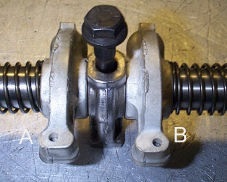
If
you must re-use original rocker shafts or rockers, it is worth considering the
following...
Why do the steel Rocker Shafts wear away and not the all
Alloy Rocker shafts that run on them?.
As an Engines internal parts start
to wear out, (Rover V8 (Cam, tappets and timing gear. first)) , Metal particles
(Swarf) are created and let loose to run around with the oil in your engine
although your filter will trap most of the larger particle oil filters
(especially cheap or old ones) will not stop this swarf from reaching the vital
engine soft metal components (Cam bearings, Main bearings Big end Bearings and
Alloy rockers) where it soon permanently imbeds itself into the soft surface of
the alloy and white metal bearings, turning them into into a very effective
abrasive surface (The end is nigh) consider this also, why do steel cranks ever
need re-grinding?. Because the white metal surfaces of the big ends and main
bearings with this abrasive quality soon gouge into the hardened steel
surface.
One very common mistake we regularly encounter is for an
engineer to replace the rocker shafts only, this is normally because although
the rocker shafts only, are showing signs of wear, and the alloy rockers do not
seem to be worn, but, beware this will not be an appropriate cure because the
re-used alloy rockers and the abrasion their surface contains will at once
start to wear out the newly fitted rocker shafts in a very short
time.
|
|
|
|
 |
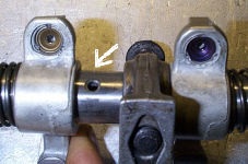 |
These bearing are your worst nightmare. Any sign of copper
means you need to do something quick.
|
Often closer inspection will show hair line cracks, don't
ignore them, as this is what you an expect..
|
If the Rocker shafts are worn, it is a sure sign that
the surface of the softer aluminium Rockers is contaminated with particles from
existing engine wear, replacing the shafts without the rockers is worse than
doing nothing,
Why?. Because new shafts will be eaten away by old rockers
and create even more damaging metal particles to cause more engine damage,
Not the best thing to have, after an expensiv
e and time consuming engine
rebuild.
If they are worn, replace them all.
| Assembling rocker
shafts |
One of our customers very kindly sent in the following on
assembling rocker shafts. We have added to it were necessary and it is now here
for you to follow when building up your rocker shafts.
|
|
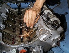
It is important to
get the oil feed holes on the new shafts in the correct orintation, with one of the posts in place the oil feed holes should
point downward. |
| Checking
& Setting Tappet pre load is becoming almost essential on all V8
rebuilds |
If you are rebuilding any
V8 engine It is becoming more and more essential to check tappet re-load
as there have been so many variants of the Rover engine components, and the
engine itself now spans over 30 years, so you can't normally "assume" anything,
So if you want to be sure of how your engine will end up. don't forget this
important issue.
Tappet pre-load is the distance between the pushrod
seat in the lifter and the circlip, when the lifter is on the heel of the cam
and the valve is closed. Not setting the lifter pre-load, will cause premature
wear, noisy valve gear, and possible engine failure.!!. Or if your lucky
"initial complete loss of compression as the valve will not be able to close
fully,
The following information assumes
that the following components are in good condition
- rockers, pushrods, valve guides and valve stems. a clearance of
.020" to a maximum of 0.60" must exist between the spring loaded pushrod seat
in the top of the lifter, and the underside of the retaining circlip. This
check should be made with the valve gear fully assembled, and the lifter empty
of oil, positioned on the lowest point, on the back of the camshaft.
The simplest way to measure the gap is by using round
wire. Use a piece .020" for the low clearance check, and a piece of
.060" for the high clearance check. Check all 16 lifters individually.
There are various ways to adjust the pre-load on the Rover V8. normally a
decrease off pre load is required and this is achieved by using the "rocker
pedestal shim kit" if the opposite applies the it would be achieved by
machining the rocker pedestals however in race and higher end applications
adjustable pushrods would be used.
 Shim Kits, are
inexpensive and include all the sizes you are likely to nee. Shim Kits, are
inexpensive and include all the sizes you are likely to nee.
Adjustable
pushrods, are 3/8" and will require the guide holes to be elongated or
opened out. Adjustable rockers can be used and are available in a pack. It
would be wise to check your valve tip heights are all reasonably the same by
putting a straight edge across them. Also, we have seen cases where the rocker
pedestal mounting points cast into the head, are not parallel to the cylinder
head face. This can make it a long tedious operation. Remember to take into
account the rocker arm ratio of approximately 1.6. Make sure the shims are
properly aligned under the pedestal so as not to block off the oil supply. Do
not use shims of different thickness on the same shaft assembly, as breakage
may occur.
Whilst most Rover or other
publication's do not touch on this subject, it is extremely important (if
assembling you own top end) to carry out this operation If you fail to do so,
all may not lost!! and maybe you'll not have no problems. but the symptoms for
those not so lucky, will be lost compression, on one or more cylinders and
noisy tappets.
 |
|
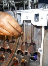
Checking tappet
pre-load can be quite difficult and as there re no special tools as
yet available for it you will need to select varying size's of welding rod or
fabricate your own |
The allowed
tolerance is 20 - 50 thou.
This is the distance measured between the top of
the tappets piston and the retaining circlip and each one needs checking
individually with the cam ideally 108.deg off its lobe. |
|
 |
 |
|
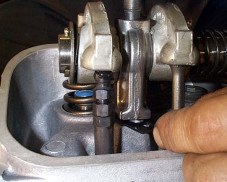
Once you have ascertained the measure
of the tappets pre-load adjustment is achieved by fitting
special pre load shims under the pedestals, but beware, the rocker
ration is 1.6 that of the clearance that needs correcting, so a 16 thou shim
will make approx. 25 though difference |
|
|
| Exhaust and intake |
Check
all manifolds and Carbs. (or injection plenum) for contamination
(especially if the old engine suffered from broken piston or valves etc.) that
can get drawn back into your new engine this includes both inlet and exhaust
manifolds and any associated parts. (Assuming you are re-using anything not
supplied new by us)
|
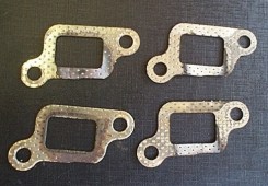
| Exhaust gasket
alignment |
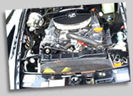
Although it may seem
obvious, which way round the fit the exhaust
gaskets. It is very possible to get it wrong, We strongly suggest you
check & double check the correct alignment, As the following 2 picture will
show, getting it wrong has a serious power loss implications
 |
|
 |
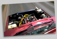
Its clear to see
just how wrong things can be. The problem
is, not, the wrong way round, but 'inside out & the wrong way round'.
!!
|
|
Surprisingly enough,
exhaust blow was not a problem but power was 40%
down minimum, especially as the rpm. increased.
|
|
|
| Timing chain
removal and refitting |
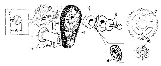 Descriptions Descriptions
| 1 - Timing
chain |
4 - Distributor
drive gear |
6 - Timing
marks |
| 2 - Camshaft
key parallel |
5 - Retaining
bolt and washer |
7 - 'FRONT'
marking |
| 3 - Distance
piece |
|
|
|
| Fuel lines |
Make
sure all fuel and oil lines (inc. oil cooler if fitted are replaced,) or
fully cleaned, always use an new air and fuel filters (of reputable quality)
and it is very important to re-check fuel filter for contamination after only a
few hours of running, always check inside the tank for fuel contamination &
replace if required.
|
|
| Fitting Kit |
|
|
 |
 |
 |
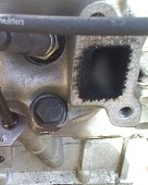
The old
blanking plug has a hole in it for the crank angle sensor that the GEM's engine
management system uses.
|
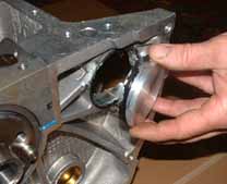
This has to
be removed for our blanking plug to be fitted. Removal of this is very easy, a
small tap with a hammer will knock the old plug out.
|
Our
blanking plug that we supply fits in place of the original and just needs some
silicon to ensure it stays in place.
|
|
 |
 |
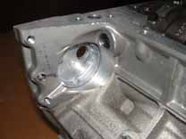
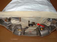
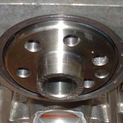
The dowel in the end
of the crank shaft has to be removed to enable the flywheel to fit correctly.
You should ensure that the crank seal is completely covered and also the bottom
end of the engine so that no swarf can contaminate it.
|
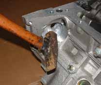
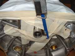
Using a hacksaw (or air hacksaw as
seen here) the dowel has to be cut of as flush to the end of the crank as
possible. |
 |
 |
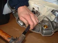
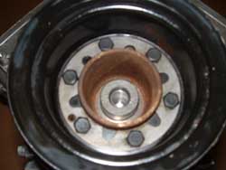
A centre punch is
then required just to knock what remains of the dowel into the hole so that it
does not protrude the face as seen in the next picture.
|
As seen here the dowel has been
cut off and then punched back into the end of the crank so that there no chance
that it can interfere with the flywheel.
|
|
 |
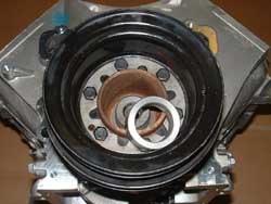 |
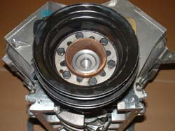
The crank is slightly
longer which means that when you do up the front pulley bolt it would not
actually come into contact with the pulley and therefor the pulley will be
loose. |
As you can see here we have made
a spacer that fits over the crank end. Now when the pulley bolt is tightened
everything is pulled together as it should be.
|
|
 |
|
|
|
|
| EFi. fuel pressure
regulators |
We have had instances, where
the EFi. fuel pressure regulator, has been fitted the wrong way round,
this caused a new engine to run only 7000 miles before its demise, due to
excessive (uncontrolled) fuel pressure It ran so rich that all cylinders where
badly Coked up and eventually cause a valve guide to drop into the cylinder
causing severe damage to the piston etc. (I hate to think what the fuel economy
was like)
. |
|
| Automatic gearbox flex
plates |
In cases of broken crank
shafts the old flex plates may contact the rear of the engine block. This will
cause stress of the metal and a failure of the flex plate after some miles
behind the new engine. Be sure to inspect the flex plate and the back of the
OLD block for signs of contact.
Aluminum bits in the ring gear are a
sign of contact, and if found, replace the flex plate no matter what. In cases
of a broken crank shaft with an automatic ALWAYS replace the flex plate if
possible, or have the original flex plate tested for cracks that can not be
seen with the naked eye.
Flex plate failure shows up as a rattle at
idle under no load that goes away when power is applied. Replacing the flex
plate means gearbox removal, so check it carefully.
|
| Automatic gearbox fitting
& Consideration to what went wrong, "before" |
Important !!!
When fitting A New transmission ( or indeed any major component similar)
to you car, please be sure all items (associated.) that may be able to transfer
contamination, including contaminated fluid/Oils or other such issues, Must be
thoroughly "Flushed Cleaned or renewed" this applies to your transmission be
sure that the oil cooler and associated parts/pipe-work/unions are impeccably
clean internally, and make sure the transfer box is cleaned out, prior to
fitting to your new Auto-box, also after you have fitted it, change (renew) the
fluid completely after only 200 - 300 or so miles This will further flush the
system, And if it comes out contaminated, do it again after another 500
miles.
Consider what caused the Old one to fail ?
Sometimes Automatic transmissions are damaged (have failed) because water gets
into the transmission oil cooler pipes where they pass through the radiator in
the radiator header, have this checked or get them renewed.
|
|
| Cooling |
Make
sure your radiator is in perfect condition, with no cooling fins rotted
and no 'Sign's' of leaks (these will show up as blue/green/white) snail trails
down the side or blue coloration from the radiator cor itself, Always replace
faulty radiators and flush out heater matrix radiator. also beware blocked
radiators. these are often one that leaks that no longer leak generally because
they have been filled up with cheap fix fluids that block everything and are
not wanted in your engines.
|
|
| Cooling System - Air
Locks |
It is also very important to
make sure the engine has no Air locks, if the system has no leaks then it
should be easy to bleed out any air that would normally be trapped in the
top hose, or highest points of the inlet manifold. (SU.s. and Strombergs have a
bleed pipe in the "V" at the top, these normally need clearing)
The
Edelbrock and Offenhauser manifolds often trap air behind the thermostat this
can be overcome by drilling a small hole in the top area of the thermostat but
is not normally required.
|
|
| Cooling systems can cause total oil
pressure loss |
Overheating problems on a
V8 engine can cause the Oil pressure relief valve to stick open and destroy
engines due to nil Oil pressure, as well as the obvious reasons not to run an
engine excessively hot, especially for any prolonged time..
|
|
| Overheating |
The best indication of
overheating on a road test would be the lack of heat coming from the
vehicles interior heater fan, and eventually noisy tappets and
'pinking', (time to stop) this is in addition the temp gauge but you can
never fully rely on these.
|
|
| Priming Oil Pump's
(engine) |
Use only Classic high
detergent style Oils. such as 'Castrol Magnatec'. or 'GTX', do not use fully
synthetic or Oil additives.
If your engine is supplied with the Oil
Pump base plate fitted, you can be assured that a priming agent (Vaseline) has
been packed into the Oil pump gears to ensure trouble free priming, if it has
not been fitted then you will need to do this yourself. It is Oil's to turn the
engine over, if the distributor is not fitted (the distributor drives the Oil
Pump) but if you forget and the distributor is fitted you will need to re-prime
the Oil pump before starting.
The best way to do this is not to worry
about starting the engine but to remove the Plugs and the coil lead and have a
highly charged battery available. the engine (with the distributor fitted) will
crank over at a speed that should allow the oil priming to be achieved in
seconds, (Oil Light out and a visual check) and unless you remove the oil pump
again then no further priming should ever be required.
|
| Priming tappets |
It is normal for the
hydraulic tappets to take some time to prime up and can often take two to
three minutes for them all to go quiet, to ensure your Oil is primed it is
always advisable to not only check that the Oil Light has gone out, and if you
have a pressure gauge then this is a good secondary source of information if in
doubt look inside (or remove a rocker cover) and check that Oil is freely
flowing from the rockers, although only a small amount is to be expected.
|
| Getting quieter |
Another good
indication is, that although you can still hear some, tappets, they will
start to quieting down right from the first moment so If tappet intensity
quickly reduces you can be sure that the Oil has primed and safely run the
engine until the last ticking stops. (normally 1 - 2 mins..)
|
|
| Using Primed Tappets |
From time to time it may be
possible to receive an engine with (or tappets) that are already partially or
fully primed this means that the engine may go quiet within seconds so this is
not a worry, however in some cases it may mean that they will need to release
some Oil before they can allow the valve'(s). to fully shut so the engine may
appear to run on only 4.7 cylinders, again do not worry as running the engine
at just above tick over will allow them to bleed down safely. a compression
check at this stage is not viable as it will give a false reading on any
cylinders that have not yet bled down
. |
|
| Some people wont listen |
We have known a customer to
Insist he had Oil (Primed) at the top of his engine, because (he said) he could
see it "through the filler hole" (he did not tell us this though), only to find
to his horror it was the oil that he had filled the engine up with, because
removal of the rocker covers proved the rest of the engine was dry of any Oil
completely. and the engine was subsequently destroyed before it had started
its life..
|
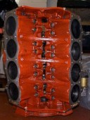
| Careful with all that
paint. |
Please refrain from painting the inside as well as the outside This was a fully
rebuilt engine as supplied to an overseas customer, needless to say, it did not
last long.
|
 |
 |
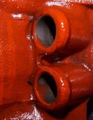 |
| Its Hard to believe anyone could
paint the engine with all the bits inside it |
The strainer is showing the red paint blockage,
this engine failed completely within 20 miles |
The strainer is showing the red paint
blockage |
|
|
| Look Behind |
On the back of the engine, if
possible Always check there is a Crank Oil seal, all Cor plugs and the
appropriate Spigot bush /Toe bearing (Manual only) in the end of the Crank
shaft as removing the engine to fit them after the engine has been fitted
(about the time when you discover its forgot) is rather annoying if not
expensive.
If we, have fitted the flywheel you can assume the above has
been checked but if you are fitting the flywheel then it is both our interest
to re-check.
|
|
| 3.5 Torque
settings |
General Torque settings for a Rover V8. engine.
| Description |
Torque setting |
| Air intake
adaptor to Carbs. |
17
lb/ft |
| Alternator
mounting bracket to cylinder head |
3/8 U.N.C bolt ::
25 lb/ft
5/16 U.N.C bolt 17 lb/ft |
| Alternator to
mounting bracket |
17
lb/ft |
| Alternator to
adjusting link |
17
lb/ft |
|
| Chain wheel to
camshaft |
45 lb/ft + lock
tight |
| Connecting rod
bolt |
35 lb/ft + lock
tight |
|
| Clutch attachment
to flywheel |
20
lb/ft |
| Cylinder head
bolts No. 1 - 10 |
70
lb/ft |
| Cylinder head
bolts No. 11 - 14 |
20 lb/ft + lock
tight |
|
| Distributor clamp
bolt |
14
lb/ft |
| Exhaust manifold
to cylinder head |
16
lb/ft |
| Fan
attachment |
9
lb/ft |
| Flexible drive
plate to starter ring |
25
lb/ft |
| Flexible drive
plate to crankshaft |
60 lb/ft + lock
tight |
| Flywheel to
crankshaft |
60 lb/ft + lock
tight |
|
|
| 4.0 & 4.6 Torque
settings |
Below are the Torque settings for 4.0 litre and 4.6 litre Rover V8
engines.
| Description |
Torque setting |
| Mains Bearings 1
- 8 |
13.5 NM first
time round then 72NM |
| Mains Bearings 9
-10 |
13.5 NM first
time round then 92 NM |
| Big
Ends |
20 NM and then
90o more. |
| Side
Bolts |
13.5 NM first
time round the 45 NM |
| Head Bolts (10
bolt head) |
25 NM then 90o
then 90o again. |
|
|
| If in doubt? |
If
in any doubt you can Phone us on +44 (0)1603 891209, Mail us or Fax us on +44 (0)1603 890330, but don't
leave it until its too late.
|
|
links to other FAQ pages
[ V8 Engine Fitting Information ]
[ Rover 3.5, 3.9, 4.2
to 4.6 Conversion ] [
LPG Conversion details ] [ Fuel Injection Section ]
[ Weber 500 & SU Carbs ]
[ Mallory Ignition
Systems ] [ General
Engine Problems ] [
General Information ] |
|
Disclaimer
Prices do not include
local EU.Tax.(VAT).
Prices & stock are subject to change without
notice. Information and advice, as always, is free.
|
|
|
|